The complete loop
A circuit needs four things: a source, a path out, a load and a path back. In most cars the positive path is a copper wire, while much of the return travels through the steel body and engine block, connected to the battery negative by ground straps. Engineers call this a chassis-return system. It saves weight and wire, but it also means the return path is shared by many circuits.
Ohm’s law explains why small changes matter. If a headlamp draws about 5 amps and a corroded ground adds just half an ohm, that connection alone consumes around 2.5 volts. The lamp receives less voltage, glows dimmer and the connection grows warm. Nothing is “broken”, yet the function fails. Kirchhoff’s voltage law adds the other half of the picture: the voltage drops around a loop always add up to the supply voltage, so missing voltage at the load must be lost somewhere else in the loop.
Circuit-path accordion
Constant feed (terminal 30)
A battery-fed supply available even with the ignition off. It powers memory functions, alarm systems and the contact side of many relays. Because it is always live, it is also a common route for parasitic drain that flattens a parked battery.
Switched feed (terminal 15 and accessory)
Supplies that become live only with the ignition or accessory position. On keyless vehicles a module often controls these feeds through relays, so “ignition on” is itself a networked decision.
High-side switching
The switch sits between the supply and the load, and the load is permanently grounded. A short to ground downstream of the switch will usually blow a fuse or trip a driver’s protection.
Low-side (ground-side) switching
The load is permanently fed and the switch completes the ground. Many module outputs that drive relay coils and solenoids work this way. A measured 12 V at both sides of a resting load is normal here, which surprises many learners.
Sensor reference and signal return
Many sensors receive a regulated 5 V reference from their module and return to a dedicated sensor ground inside that module rather than the body. Several sensors may share one reference, so a short in one can disable others.
Fuses protect the wire
A fuse is sized for the wire it protects, not for the device at the end. If a fuse blows, it is evidence that more current flowed than that wire should carry, whether from a short to ground, a seized motor or a failing component. Fitting a larger fuse removes the evidence and the protection together.
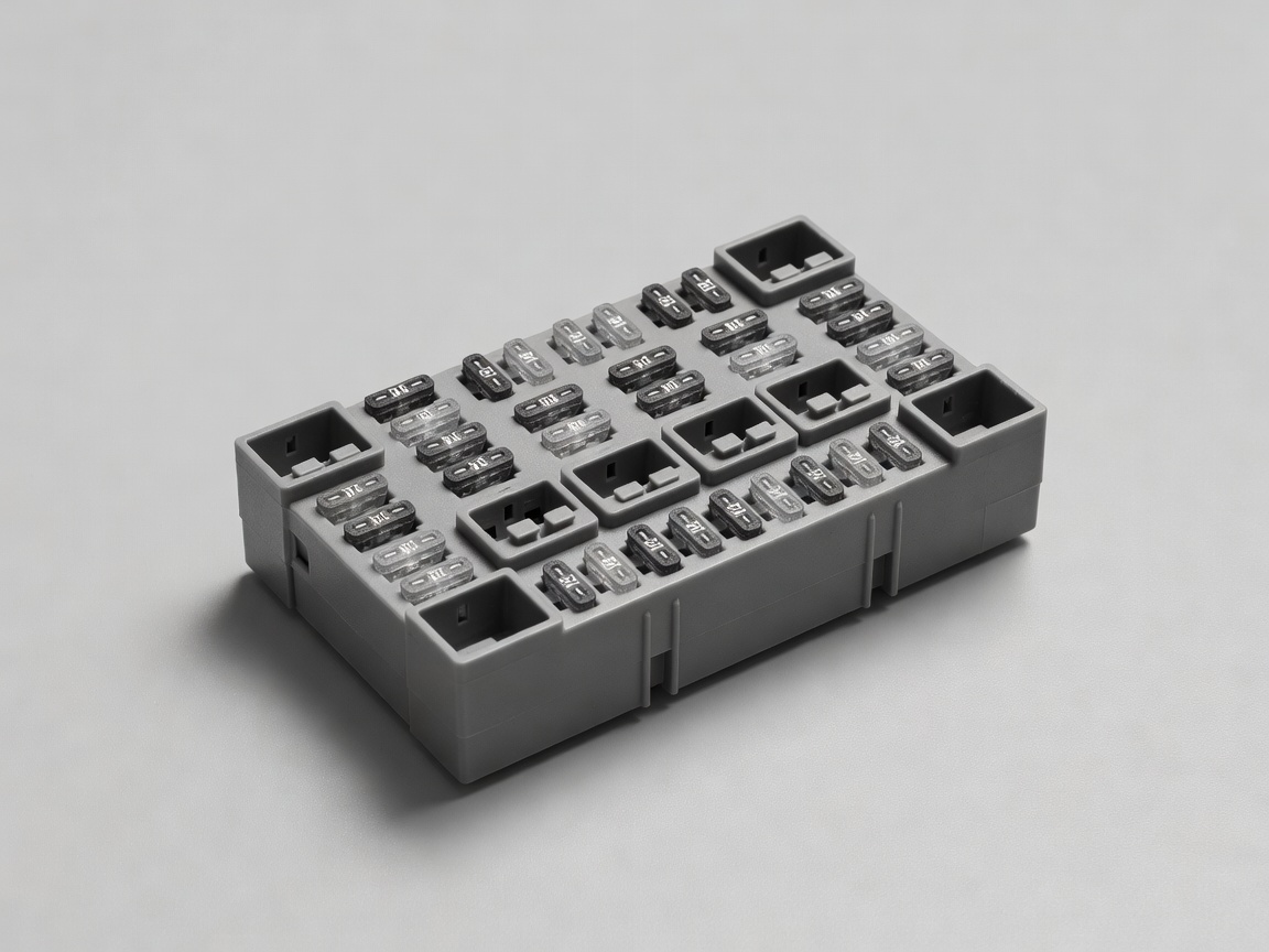
Blade fuses come in sizes often called micro, mini, standard and maxi, with colour codes linked to their ratings. Heavier feeds use fusible links or bolt-down fuses near the battery. Many modern distribution boxes add current-sensing electronics that report overloads to a module.
Connectors: where circuits usually fail
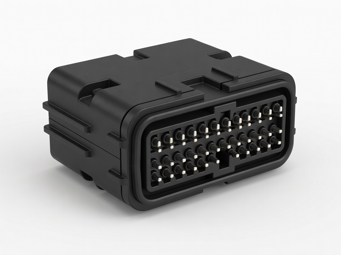
Wire rarely breaks in the middle of a harness. Problems gather where wires end: crimped terminals, connector pins and ground eyelets. Vibration can cause fretting, a microscopic rubbing that builds oxide on tin-plated contacts. Moisture can creep past a damaged seal. A terminal that has been probed with an oversized meter lead may lose its grip, a fault technicians check with “pin drag” using a matching terminal.
Because connectors join systems, a single loose terminal can produce symptoms that seem to belong to a sensor, a module and a network at once.
Voltage drop: measuring the loop under load
Resistance tests with the circuit off can miss problems because a single strand can show continuity yet fail to carry real current. Voltage drop testing measures the circuit while it works. With the load running, a meter placed across a section of wire, a connection or a ground shows how much voltage that section consumes. Healthy connections usually lose very little; exact acceptable figures vary by circuit and manufacturer, so treat published service limits as the reference.