Why a small current controls a large one
A cooling fan or fuel pump can draw well over ten amps. Running that current through a dashboard switch or a module’s circuit board would require heavy wiring routed through the cabin and components large enough to survive the heat and arcing. A relay solves this by separating decision from delivery. The control side needs only enough current to magnetise a coil, often around a tenth to a fifth of an amp in a typical 12 V mini relay. The load side carries the heavy current over a short, thick path from the fuse box to the device.
This separation is why relays are best understood as part of a system. The coil circuit belongs to the switch or control module that commands it. The contact circuit belongs to the power distribution system and the load. A fault on either side stops the function, but the evidence for each is gathered in a different place.
Relay anatomy panel
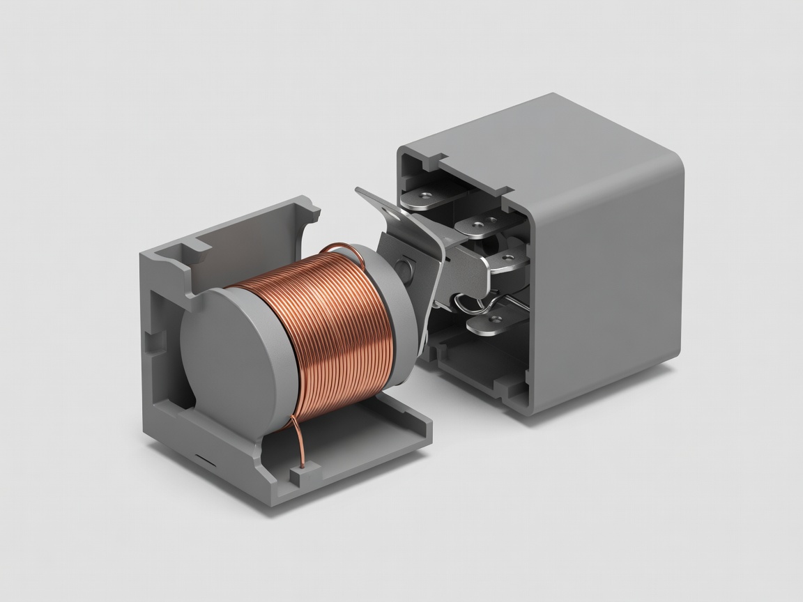
- 30Common. Usually a fused battery feed; the input to the switching contact.
- 85Coil end. Frequently the ground side, sometimes switched by a module.
- 86Coil end. Frequently the switched positive. Polarity matters if a diode is fitted.
- 87Normally open output. Joins 30 when the coil is energised.
- 87aNormally closed output. Joined to 30 at rest on changeover relays.
Terminal numbers printed on a relay are a convention, not a guarantee of how a particular vehicle wires them. Check the wiring diagram for the exact car.
Relay types and where they appear
Normally open (four-pin) relays
The most common type. At rest the contacts are open, so the load is off. Energising the coil closes them. Horns, fans, fuel pumps and heated rear windows commonly use this layout.
Changeover (five-pin) relays
A single moving contact rests against 87a and moves to 87 when energised. This lets one relay choose between two paths, such as switching a fan between low and high speed arrangements or reversing a motor with a pair of relays.
Relays with suppression diodes or resistors
When coil current stops, the collapsing magnetic field produces a voltage spike that can harm module outputs. A diode or resistor across the coil absorbs it. A diode-equipped relay installed with reversed coil polarity can short the control circuit, which is why look-alike relays are not always interchangeable.
Micro, mini and PCB-mounted relays
Footprint and current rating vary. Many vehicles also solder relays directly to circuit boards inside fuse boxes or body modules, where they cannot be swapped individually.
Solid-state switching
Many newer designs replace mechanical relays with semiconductor high-side or low-side drivers inside modules. These have no moving parts, can measure their own current and can report open or short circuits as fault codes, but there is nothing to hear click.
How the relay fits the system
Follow a fan request from beginning to end. A temperature sensor changes resistance. The engine module reads it, compares it with its programming and switches the coil circuit, usually by providing a ground path through a transistor. The coil pulls the armature, the contacts close and fused battery current flows from terminal 30 to 87, along the output wire to the motor and back through a ground point. Six or more connections take part, and any one of them can be the weak link.
That is why replacing a relay because the fan does not run is a guess rather than a diagnosis. The relay may be perfect while the fuse, the output wire, the motor brushes or the ground strap are at fault. Equally, a module may never command the relay because a sensor or network message is missing.
Relay failure patterns
| Observation | What it may indicate | Next evidence |
|---|---|---|
| No click, no load | No coil supply, no coil ground or open coil | Voltage across 85 and 86 when commanded |
| Click, no load | Burnt contacts, blown load fuse, open output or load fault | Voltage at 87 and at the load under command |
| Load runs constantly | Welded contacts or a control circuit stuck on | Does the load stop with the relay removed? |
| Load works intermittently | Pitted contacts, loose socket terminal, heat | Voltage drop across the contacts under load |